For the longest time I thought logic modules felt really complicated. I couldn’t imagine how I would use them in regular patches. Then one day I had a completely random gate pattern triggering a plucky sound. It was a bit over the top and chaotic. I thought, “what if those randomly occurring gates were a little more in time?” I learned that if I run my gate through a VCA and send a clock to the CV IN, then my random gates will only happen when the clock is active. Figuring out how AND logic works helped me realize it’s incredibly useful and a lot simpler than I had initially thought. I want to create that same kind of “AHA!” moment I had to make logic not only approachable, but desirable by all.
Why should I care about Logic Modules?
They take input from existing sources and create something new! It really is that simple: input two existing signals and you’ll get a related result at the output. It’s almost like they are expanders for your modules. When your sequencer runs out of rhythm lanes, add a small logic module for new patterns. Logic modules are invaluable for adding this kind of complexity and depth to your patches, but without very much effort at all.
OK, so how’s Logic work?
First, I am writing about binary logic, where something is either ON or OFF. Some folks that are already well versed in Boolean logic may be resistant to the way I explain things because they’ve learned in a different way. I am a musician, not a programmer or mathematician, and I’ve taken a slightly altered approach to make it easier for me, and hopefully others, to understand.
I touched on the concept in the previous section, two signals combined in some way make a third. That is an oversimplified way to look at it, so let’s break it down into digestible chunks.
Typically, logic is used to perform a function on two input gate signals we will call A and B respectively. I’ll be using the words “high” and “low” to represent when a gate is present or absent. The main available types of operations are AND, OR, XOR with lesser-used operations, NAND, NOR, XNOR.
The following charts are called truth tables, of which there are many examples elsewhere if mine do not appeal to you.
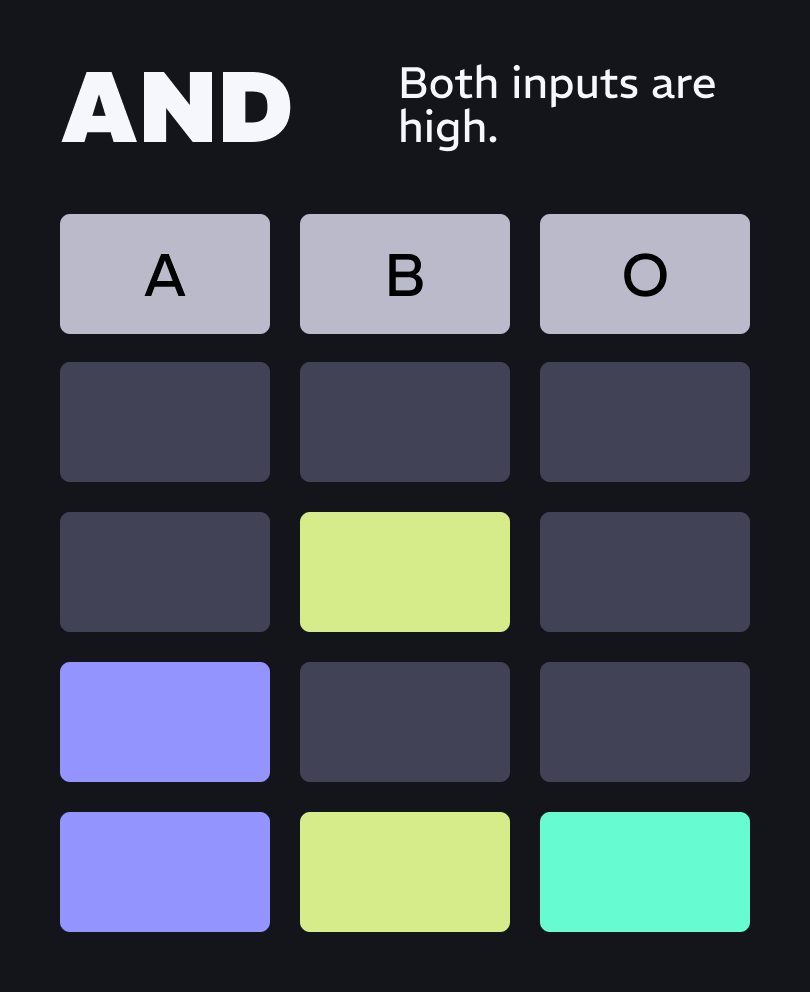
AND: Both inputs are high.
Said another way, when each gate occurs at the same time and only when both are active.
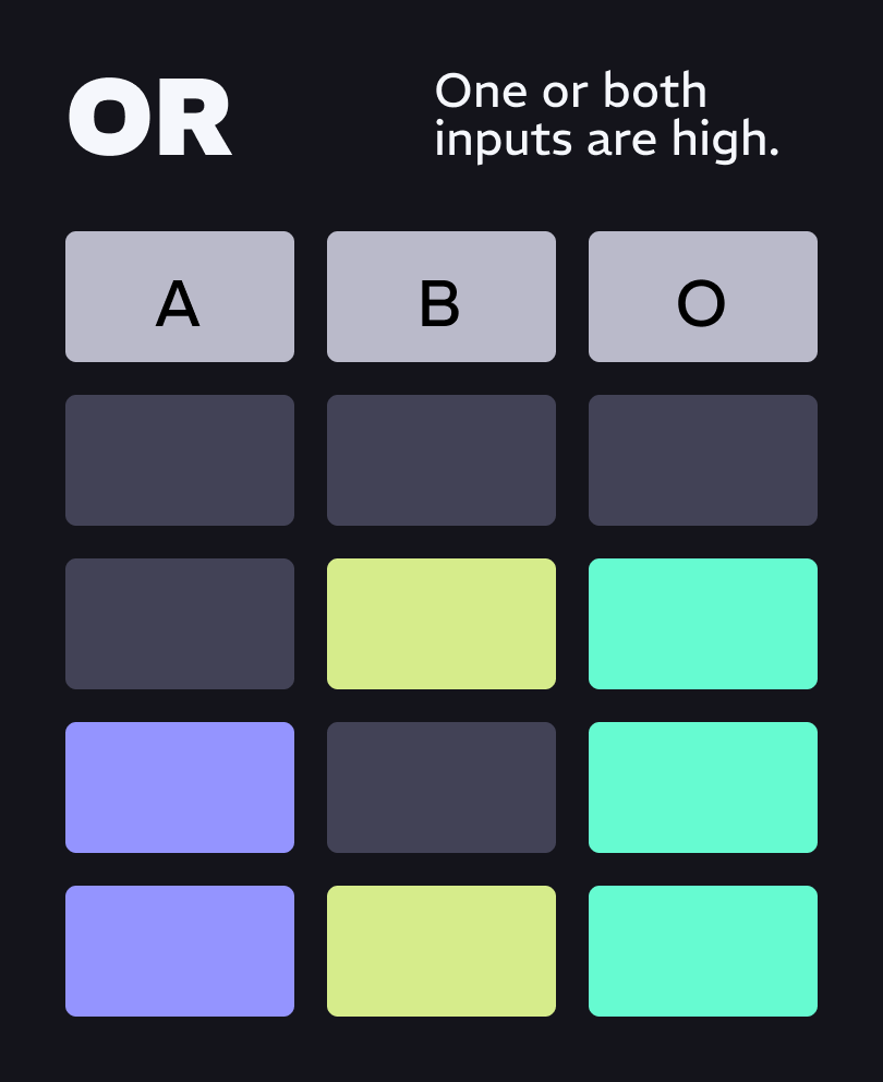
OR: One or both inputs are high.
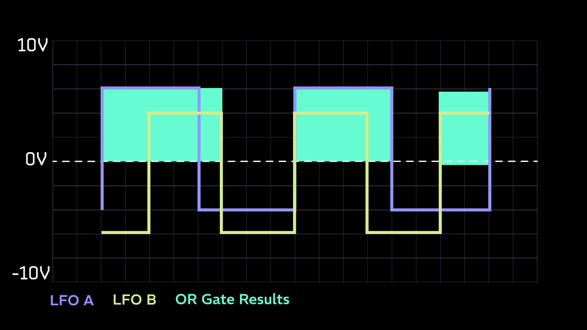
Said another way, this is a mixture of both inputs. Though if two high gates of different lengths overlap, that gate will be the full width of both.
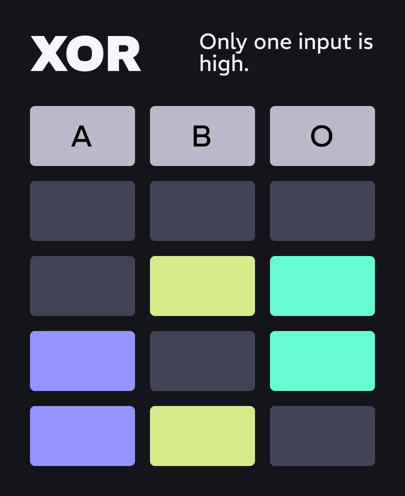
XOR: Only one input is high.
Said another way, if both are off, or both are on at the same time then nothing is passed through. Only when one is active by its lonesome self will it pass.
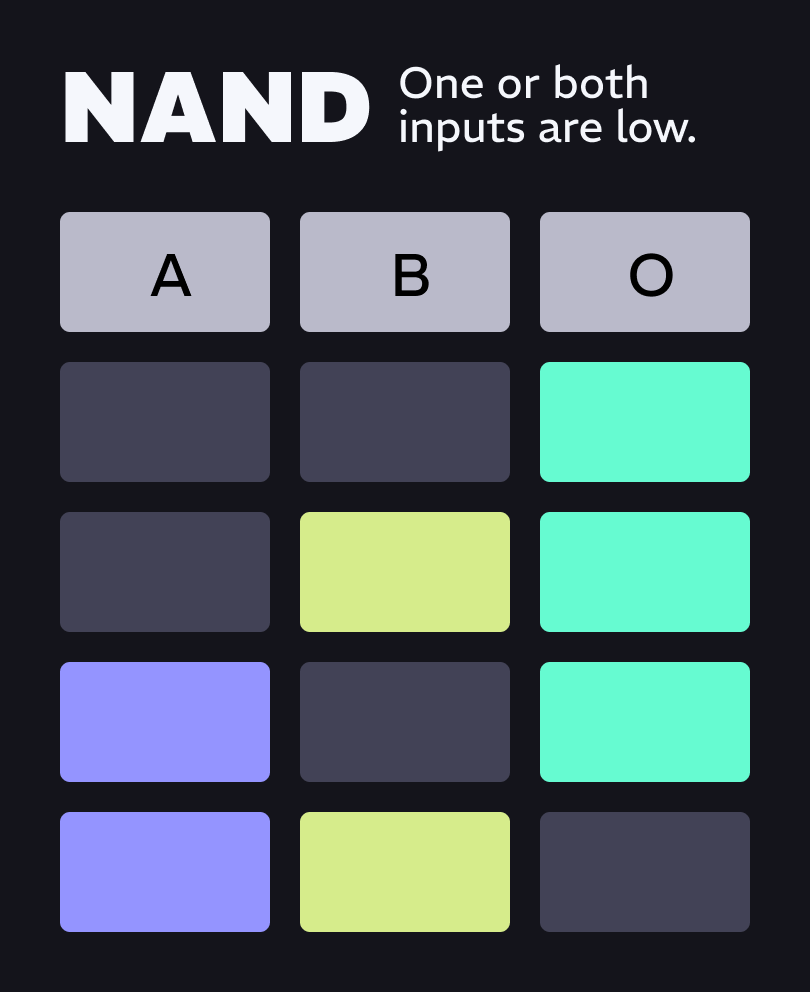
NAND: One or both inputs are low.
OK, this is really just the opposite of AND. If both inputs are high, then nothing is passed. Otherwise, it passes everything.
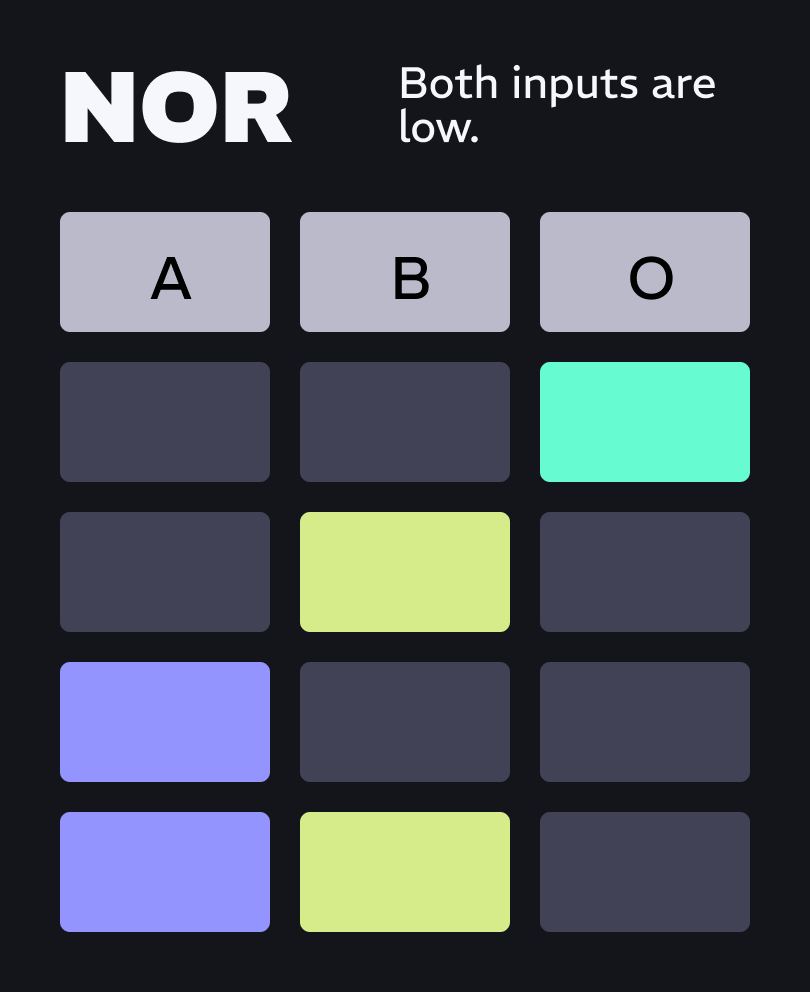
NOR: Both inputs are low.
This happens to be the opposite of OR. It only creates a gate when everything is low. This is likely my favorite because it is a quick way to fill gaps with a new sound.
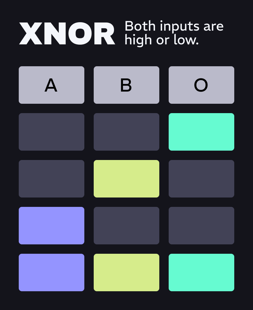
XNOR: Both inputs are high or low.
You guessed it, this is the opposite of XOR. They both need to be on or off together, but not alone. Essentially, if the states are the same, then a high gate is created.
“Whoa, whoa, whoa, slow down. Too many highs and lows to compute,” said a reader. Ok, let’s look at this in step sequencer terms. In the next chart I show an 8-step sequence for A and B. Below that is the output sequence you get from each type of logic.
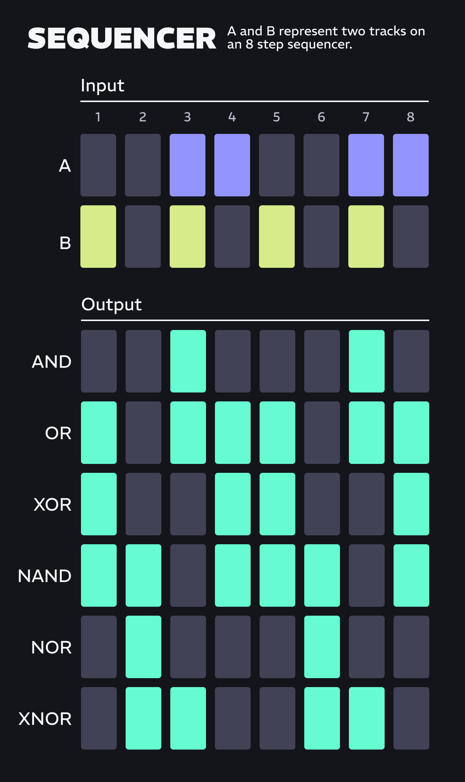
I hope this has given you a good basis for understanding. Now, let’s put this into practice.
Practical Patchables
First, you probably already have a few logic modules, sort of. You can fake an AND, OR, and NOT.
AND: A VCA is all you need. Patch one signal to the IN and another signal to the CV IN. Think about it, if gates are going to the IN you will only hear them when gates going to the CV IN open the VCA.

OR: A mixer is all you need. Patch gates into channel 1 and patch some other gates into channels 2. OR is when one or both gates are active. That means neither gate is stopping the other from passing.
NOT: Send a GATE into an inverter and then it is the opposite of what it was. Therefore, it is a NOT. However, inverting a positive-only GATE signal will make it fully negative, and to make it useful as a gate, it should be above 0V. So you will need to offset the inverted copy.

Technically, you should be able to make any logic gate from AND and NOT, but it gets really complicated really fast and you’ll end up needing lots of VCAs, offsets, and inverters. So it is a lot easier just to get and use a logic module.
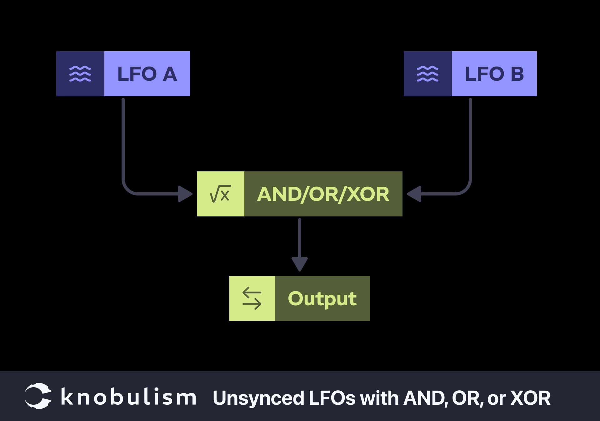
Comparing Two Unsynced LFOs with AND, OR, and XOR
This patch demonstrates the different outputs generated by AND, OR, and XOR gates when processing two unsynced square wave LFOs. You can think of the LFOs simply as two clocks running at different speeds that are not multiplications or divisions.
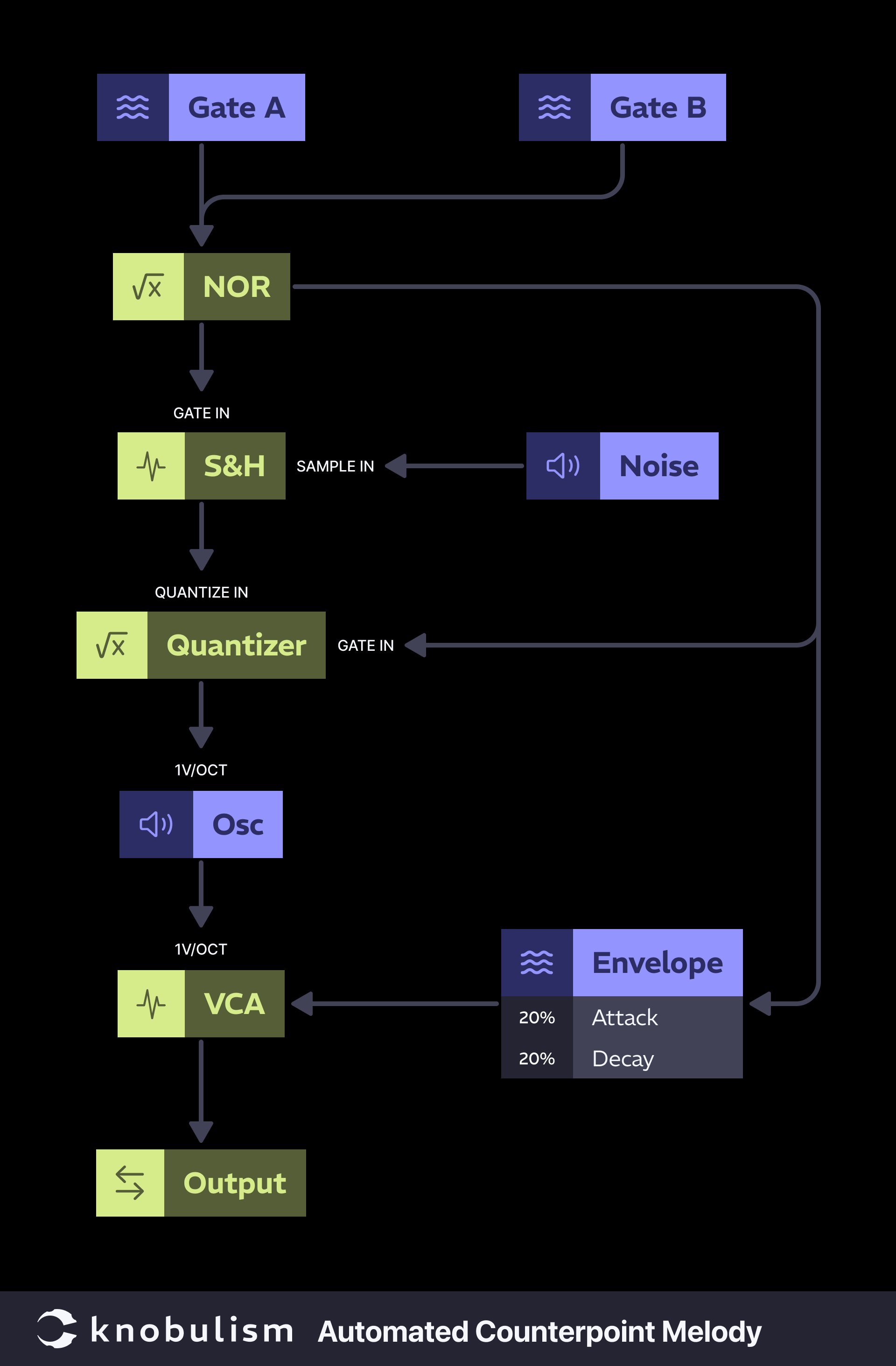
Automated Counterpoint Melody
Using the gate signal for your main melody as one logic input and your bass as the other to extract a gate controlling a quantized sample and hold will automatically fill the gaps with in-tune notes.
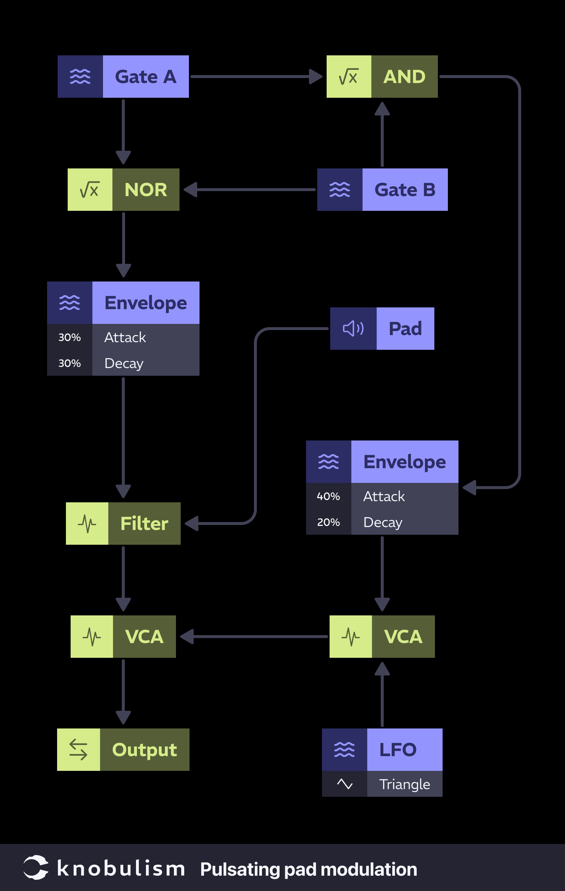
Pulsating Pad Modulation
Similar to the previous patch, use existing gates to trigger modulation sources, creating dynamic modulations that react to other parts of your patch. I suggest either from your Kick and Snare, or any two you think would be fun.
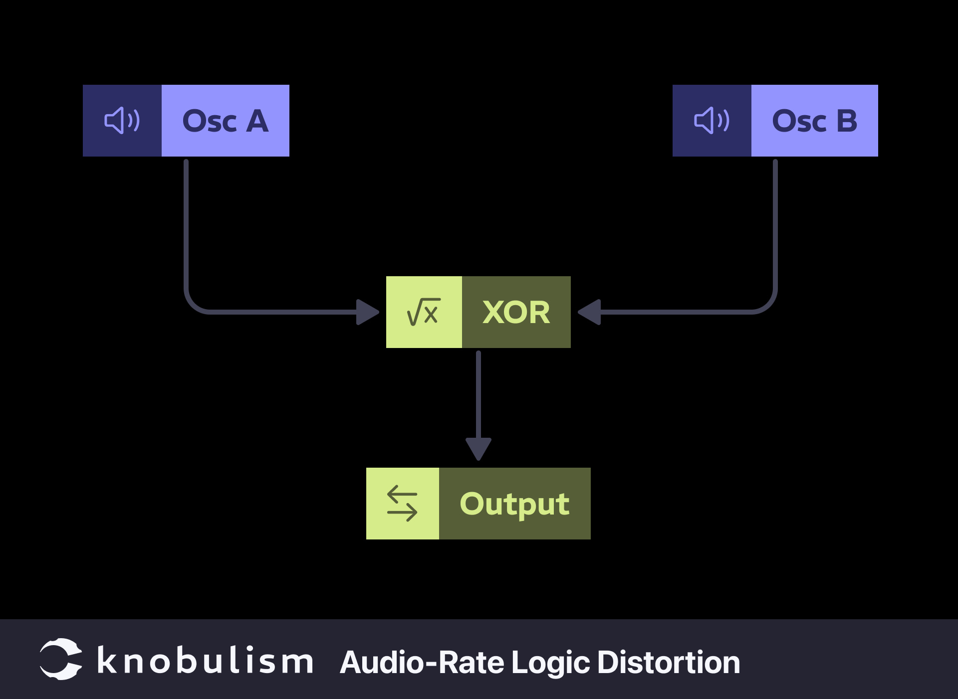
Audio-Rate Logic Distortion
Use logic gates at audio rates to create unique distortion effects. Generates non-linear distortion effects, producing harsh and complex tones killer for experimental sound design.
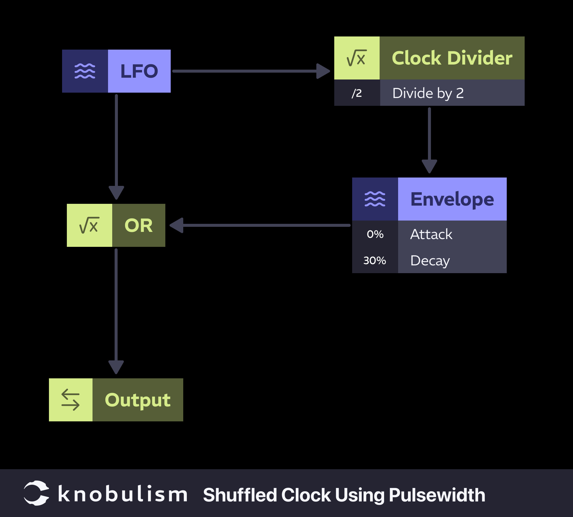
Shuffled Clock Using Pulsewidth
Using only an LFO, clock divider, AD envelope, and OR logic you can make a quick and dirty shuffled clock. It is leveraging a concept I wrote about in “Pulses, Gates & Triggers: What’s the Diff?” where you can modify the length of gates with an envelope.
Experimentation is key when working with logic modules. Don’t be afraid to try unconventional patching techniques, as many great sequences come from happy accidents. Use modulation sources creatively to add variation and interest to your sequences, and pay attention to clock signals and timing, as these are crucial for creating coherent sequences. Document your patches and settings to replicate and build upon successful sequences.
Subscribe to our newsletter, follow us on social media, and check out related articles for more tips and techniques. Share your thoughts and experiences in the comments below!




1 thought on “Logic modules aren’t only for Vulcans.”