I’ve been wanting to improve my patch charts so they are easier to understand, easier to view, and more visually pleasing. During this process, I realized it would make sense to explain the new charts and also share some basic signal flow concepts.
Jacks, Inputs, and Outputs: How Does That All Work?
Connecting your modular synth can be a bit daunting with all those jacks and cables, but it’s simpler than it seems. The general rule is to go from output to input. Outputs are designed to send signals, while inputs are designed to receive them. But beware, plugging an output signal into another output can cause issues, potentially damaging your modules or creating unwanted noise. This is a bit less common now as most manufactures have a protective circuit in place, but, better safe than sorry.
The Basics: What’s Flowing Through Those Cables?
In your Eurorack system, every cable you patch is carrying voltage. That’s it. Simple as that. But your brain (and ears) interpret voltage differently depending on its frequency. At higher frequency rates (20 Hz – 20 kHz) the voltage signal becomes audible. At lower rates (below 20 Hz) we can no longer hear the signal. Regardless of whether voltage is above or below our hearing range, it still remains voltage.
Some modules generate voltage signals, which I will creatively name, “Generators”! Other modules alter or modify voltage, which I will shockingly name, “Modifiers”. I’ve seen other documents and explanations that break this down into: Audio Generators, CV Generators, Audio Modifiers, and CV Modifiers. This model breaks the moment you decide to use a VCO (Audio Generator) as CV. By dropping the “audio” or “CV” distinction, that same VCO is now semantically capable of being audio or CV.
Voltage Types: AC vs. DC
In modular synthesis, you’ll encounter both AC (alternating current) and DC (direct current) signals. AC signals, which oscillate around zero volts, are typically used for audio. DC signals, which stay above or below zero volts, are used for control voltages (CV). I touch on this in a previous article Feedback Fundamentals.
Generators: The Source of It All
A good way to go one category deeper is to split generators into the functions for which they are used. Is the generator used for audio, or is it used for modulation? This distinction helps separate both concepts clearly, provides more flexibility, and enhances clarity of patch descriptions.
- Audio Sources: Oscillators (VCOs, DCOs) pumping out various waveforms. Noise generators creating hissy, fuzzy goodness. Audio-rate function generators for complex tones.
- Modulation Sources: LFOs (Low Frequency Oscillators) for rhythmic modulation. Envelope generators shaping the contour of sounds. Sequencers for repeating patterns. Random voltage generators adding unpredictability. Clock generators keeping everything in sync.
The magic here? These categories aren’t set in stone. Crank up an LFO’s frequency, and suddenly it’s in audio territory. Slow down an oscillator, and you’ve got yourself a unique CV source.
Modifiers: Shaping and Sculpting
Once you’ve got your signals generated, it’s time to shape them. This is where Modifiers come into play:
- Signal Processors: These bad boys alter your voltage directly. Filters, VCAs, waveshapers, and whatnot, they’re all here to twist and mangle your audio or CV in delightful ways.
- Logic and Math: Alter tempo, rhythm, pitch, or extract gates and envelopes from other signals. Logic modules, comparators, and quantizers let you create complex relationships between your voltages.
- Utilities: The unsung heroes of any patch. Mixers, attenuators, multiples, they might not be glamorous, but damn if they aren’t essential.
- Control Interfaces: This is where you get hands-on. Touch plates, joysticks, pressure-sensitive pads, they’re your gateway to expressive control.
- Input/Output: MIDI-to-CV converters, audio I/O modules, even computer interfaces—these are your bridge to the outside world.
Here is a chart that details these categorizations. The module types may not be exhaustive, but anything not detailed will definitely fit into the parent categories.

Signal Flow Example Patches
Really, any patches will work to illustrate signal flow, so in this case, I am going to focus on two things:
- My new chart designs to see how well they work.
- Patches that illustrate how CV and audio are all just voltage at different speeds.
Let’s get patching!
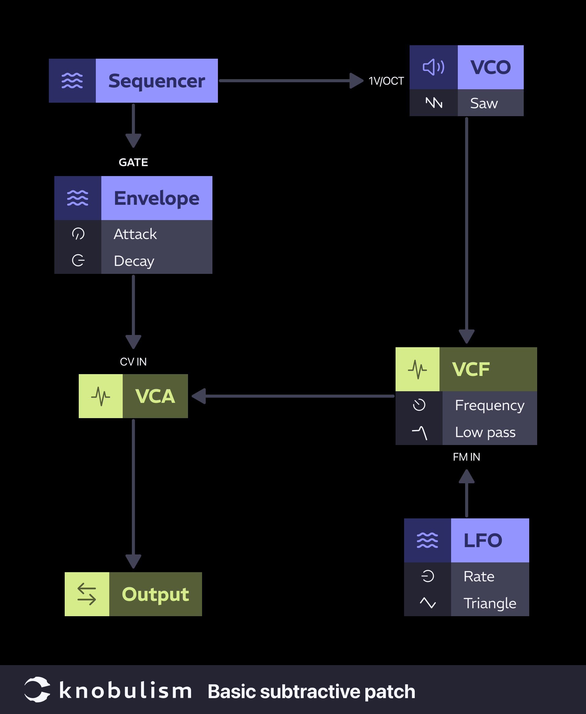
Basic Subtractive Patch:
This illustrates a very simple subtractive synthesis patch and its signal flow. It is a good place to start to understand the relationship between inputs, outputs, CV, audio, jacks, and cables.
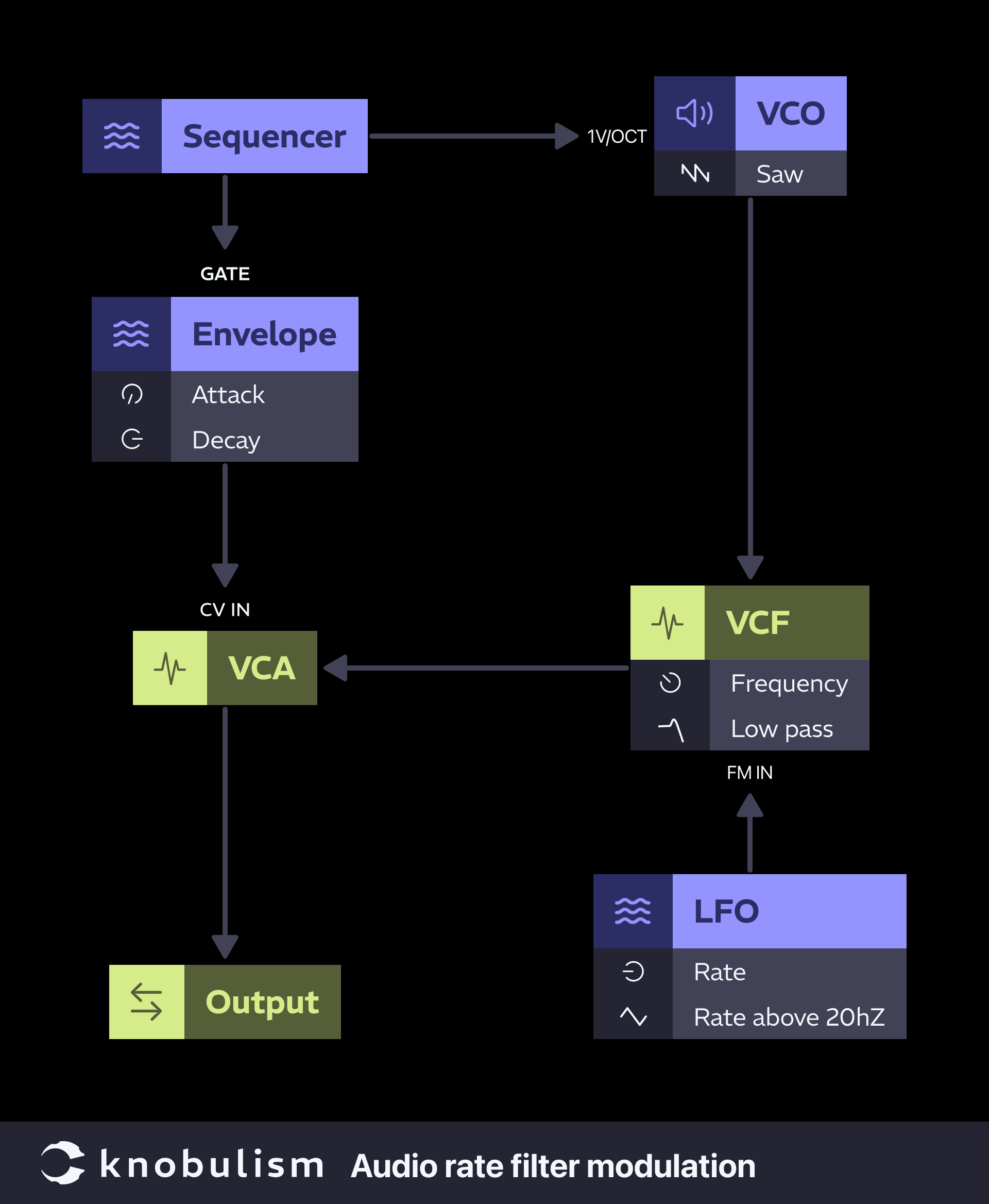
Subtractive Patch, Audio Rate Filter Modulation:
This patch is exactly the same as the previous but shows how the same modulation source can change from CV rates to audio rates.
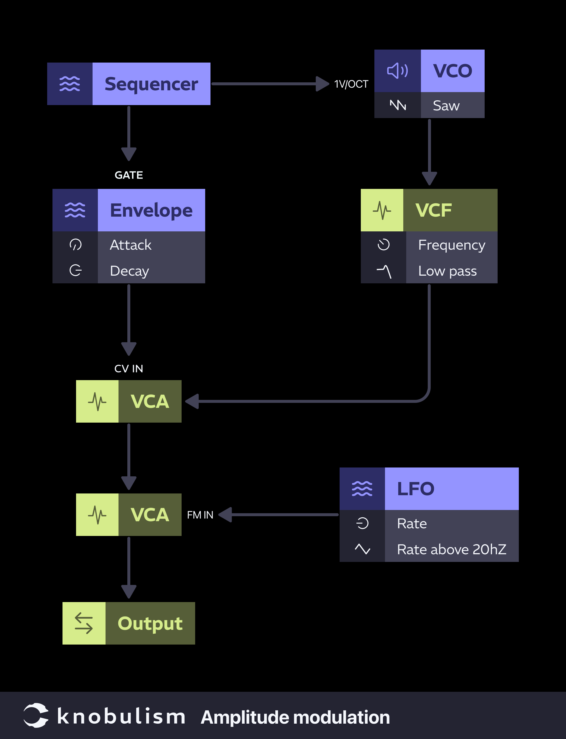
Amplitude Modulation
Further expanding the patch above, add one more VCA before the final output. Then move your LFO output (or use another LFO) to the VCA CV in. Try slower sub-audio rates, notice it creates a tremolo effect. As always, if the effect is too strong, attenuate your modulation. Now increase the speed of the LFO until you hit audio rate and notice how the sound begins to get distorted and metallic sounding.
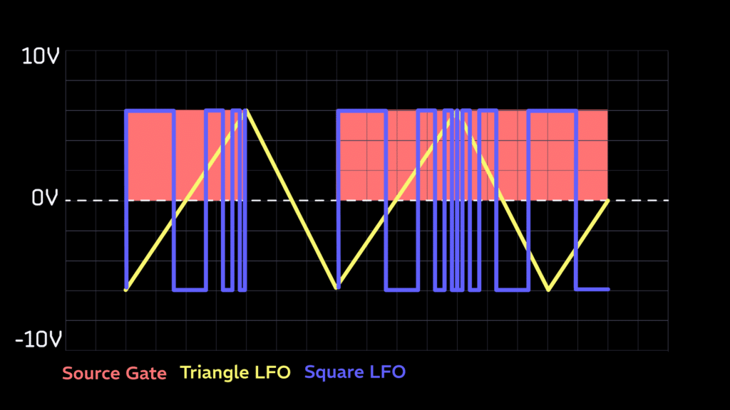
Rhythmic Ramping Gates:
This patch processes a gate source to create a repeating gate where the rate is either accelerating or decelerating. By controlling the rate of square wave LFO with a second triangle LFO the speed of the square wave will increase and decrease giving us ramping gates. What makes this effect feel in time with your sequence is the duration it is active. The length of the sequencer source gate determines the when and how long this effect is active by opening a VCA to allow the ramping gates to pass. Depending on the level of the triangle wave LFO, the output gate can vary from sub-audio into audio ranges.
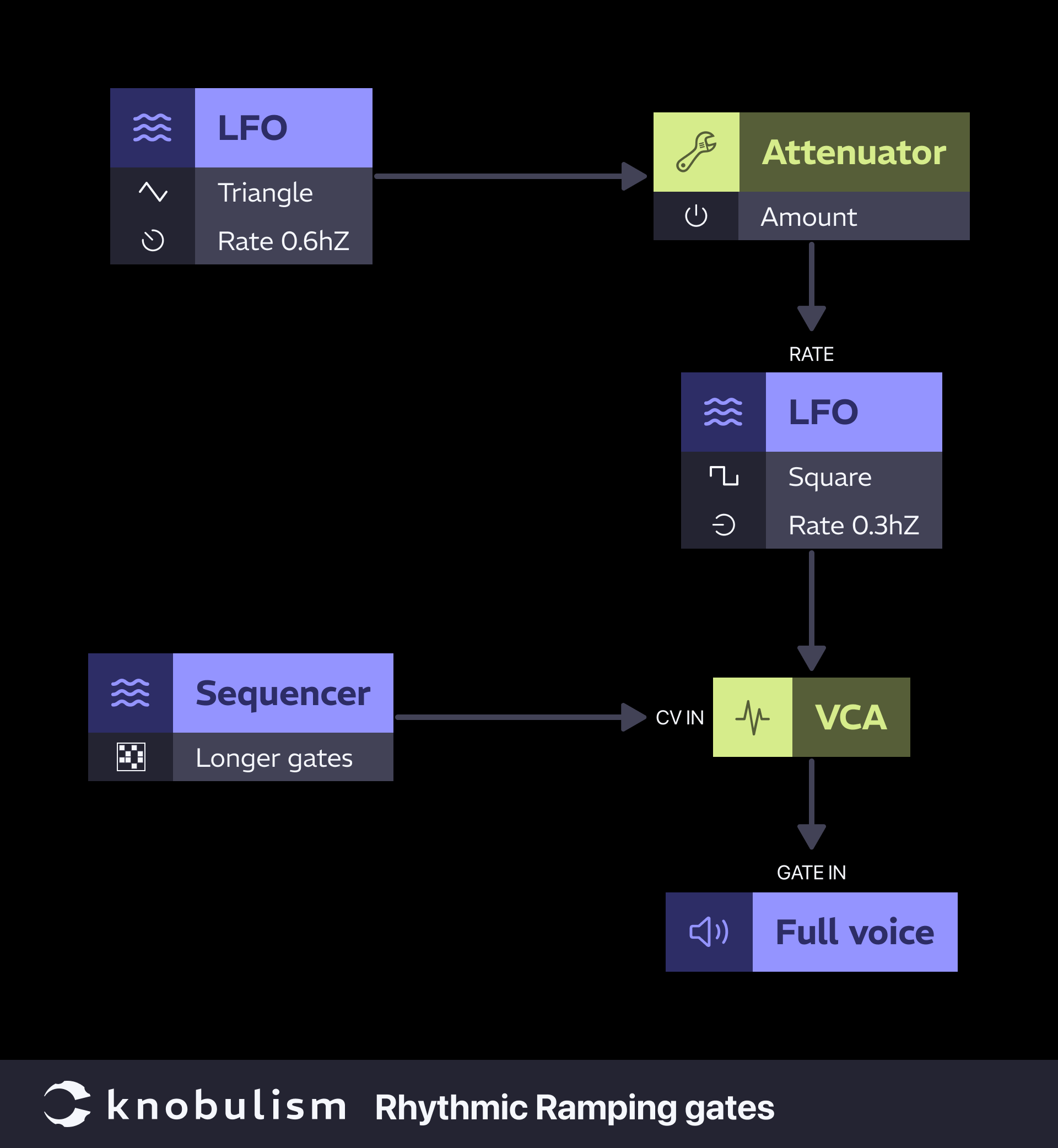
The following chart illustrates how the source gate only allows the square through when it is active. It also shows how the rate of the square is affected by the triangle.
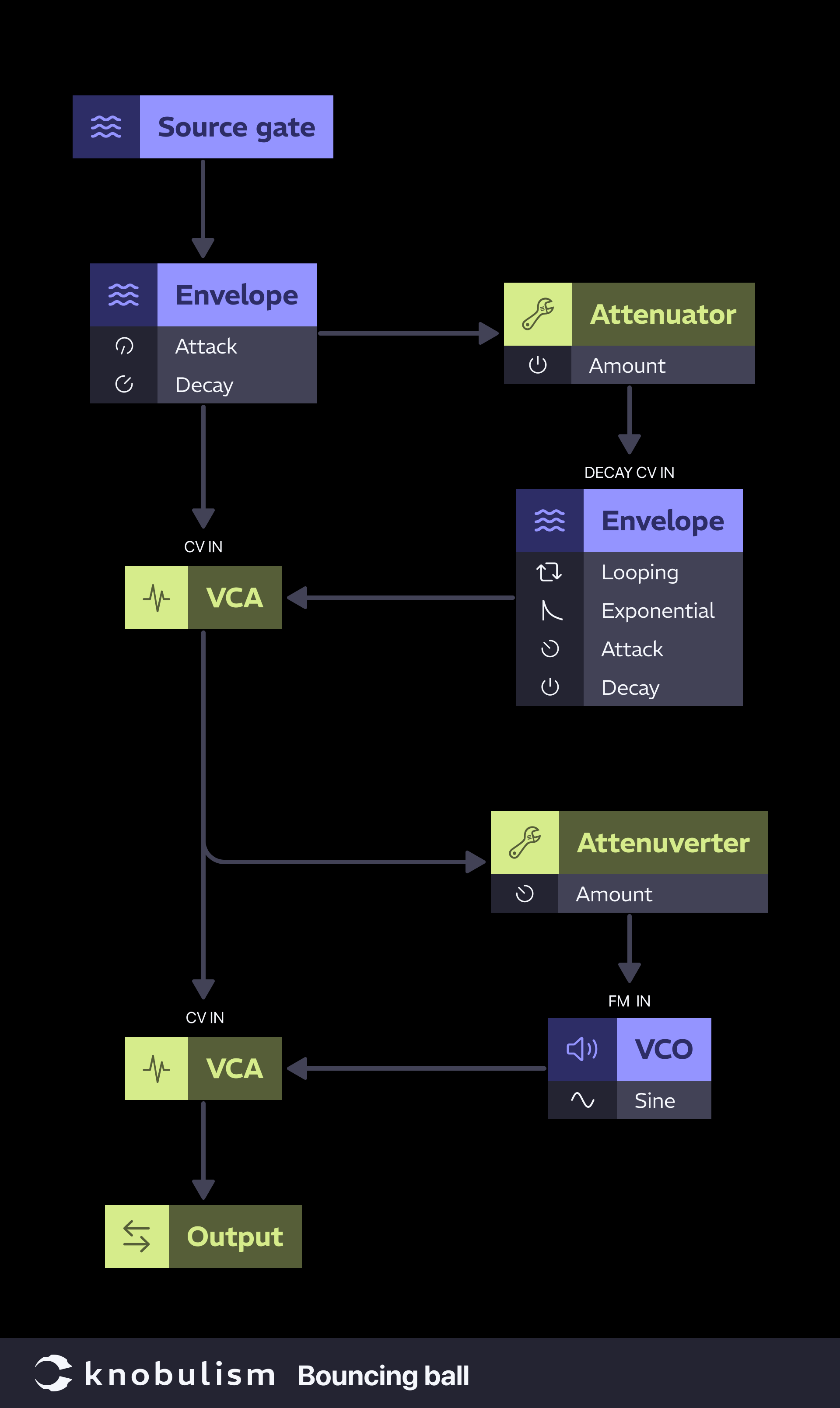
Bouncing Ball Patch:
Similar to the exponential gates but instead of the gates increasing in rate we will increase the speed of a cycling envelope by modulating the decay time with another envelope. One optional, but cool sounding trick here is to mult the looping AD and patch it to the VCA and the VCO FM input. If you use an attenuverter to reduce and invert the signal a little, you get a little rising pitch sweep that makes the ball sound more plastic.
Understanding modular synth signal flow is crucial for mastering patching and creating more complex sounds. By recognizing that it’s all just voltage, whether for audio or control, you can unlock new creative possibilities. Generators provide the raw material, while modifiers shape and sculpt it into something unique. Experiment with different patches and see how these concepts enhance your modular synth journey. Happy patching!


New diagrams looking great and easy to follow!
Thank you so much. It has been a mission of mine to create a patch design system that meets a lot of requirements:
– Logical module categorization system
– ADA compliant
– Will apply to any synthesizer
– Easy to follow
– Visible on desktop and mobile
– Primarily top down, left to right flow
– Output and input labels (just solved this one in the newest article)
– Parameter types and values
Basically my goal is the have the best flow charts that have ever existed in all of synth history.